Import Information from an AutoCAD® File
You have the capability to easily import 2D AutoCAD files. This feature enables you to transform your 2D AutoCAD projects into dynamic and interactive 3D presentations with just a few simple clicks.
Information from DWG files, the native file format for Autodesk’s AutoCAD software, can be copied directly into Vip3D projects. Vip3D can also import information from DXF files. This allows you to import templates, landscaping symbols, and whole 2D design projects into Vip3D.
Importing AutoCAD
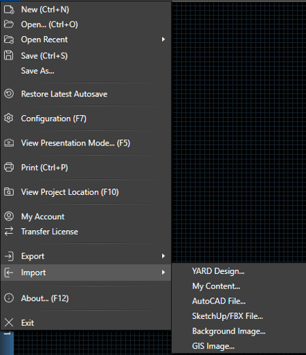
There are two ways to import an AutoCAD file. You can go to the Application Button Menu, select Import, and then select AutoCAD file.
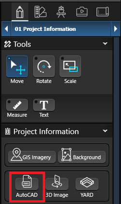
Or you can use the Import AutoCAD Drawing button in Stage 1: Project Information in the Panel.
AutoCAD File Formats: Only AutoCAD files in the DWG or DXF formats can be imported. Files in other formats will need to be converted before being imported.
How the Information is Imported: The software only copies the information from the AutoCAD file. It does not actually open the file. Nothing done in the software will change the original AutoCAD file. Also any changes made to the file in AutoCAD will not be reflected in the software unless the file is imported again.
Information that Will Not Import: Only lines and symbols will be imported. Text, lines colors, styles, and weights as well as other information will not be imported. Object heights and depths are not imported and will have to be set in the Stage Tab of the Panel.
AutoCAD File Name: The name of the imported AutoCAD file will appear in the top left of the screen in parentheses after the project file name. The name will remain there until either the AutoCAD view is closed.
NOTE: Imported AutoCAD files are saved with the project sav file.
AutoCAD View
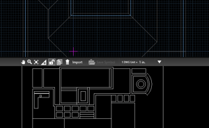
Once an AutoCAD file has been imported, the 2D viewport will display a split screen. The regular grid is now the top half of the screen and the contents of the AutoCAD file are displayed in the bottom half of the screen.
NOTE: The AutoCAD view does not appear on all stages. It only appears on stages with drawing tools.
Adjusting and Closing the AutoCAD View: The AutoCAD view can be collapsed by pressing the down arrow in the top right of the AutoCAD view. Pressing the down arrow again will expand the menu. The height of the AutoCAD view can be adjusted by holding down the left mouse button on the center bar and dragging the view up or down. The AutoCAD view may be closed by pressing the red X.
NOTE: Closing the AutoCAD view will remove the AutoCAD file from the project. Once you close the view, you will need to import the AutoCAD file again.
Moving within the Views: The AutoCAD view has the same basic pan and zoom controls as the grid. The grid and the AutoCAD view may be locked to the reference points so that both will pan and zoom together or the views may be independent of each other. Remember that lines from the AutoCAD view will always import based on the location of the reference points, not the section of the grid that is currently being viewed. The grid and the AutoCAD view may be locked using the lock button in the AutoCAD view menu.
Reference Points: The reference points are represented by pink plus signs. One point appears in the AutoCAD view and one point appears in the grid. When lines are imported they will always appear relative to the placement of the reference point. The reference points may be hidden using the button in the AutoCAD view menu.
Importing from the AutoCAD View into Vip3D: Any selected line or shape may be imported from the AutoCAD view into the Vip3D project by using the Import button. Unlike Vip3D, many shapes in AutoCAD are incomplete. In order for these imported shapes to appear in 3D they must be completed. This can be done by using the Group button to weld the lines together or by using the Line and Arc tools to complete the shapes.
NOTE: Make sure to set the AutoCAD scale before importing.
AutoCAD View Menu
The AutoCAD View Menu is located in the center at the top of the AutoCAD view.
 Pan: Pan allows you to shift the AutoCAD view left to right and up and down.
This helps you to view everything if the plan in the AutoCAD file is larger than the view. You can also pan by holding down the center mouse wheel. Pan works exactly the same in the AutoCAD view as it does in the grid.
 Zoom: Zoom allows you to zoom the AutoCAD view in and out.
You can also zoom by using the mouse wheel. Zoom works exactly the same in the AutoCAD view as it does in the grid.
 Zoom to Extents: Zoom to Extents will zoom the AutoCAD view so that a currently selected object fills the view.
If nothing is selected, it will zoom out so that all items can be seen. Zoom to Extents works exactly the same in the AutoCAD view as it does in the grid.
 Hide/Unhide Reference Points: This button will hide the reference points. If the reference points are hidden, this button will reveal them.
 Lock AutoCAD View to 2D View: This button will lock the AutoCAD view to the grid of the 2D view so that each view will move and scale at the same time.
 Display AutoCAD View as Background Image: This button will collapse the AutoCAD view and display the AutoCAD file as a background image.
This allows the AutoCAD file to be used as guide to trace lines which would not be useful to import. The Display AutoCAD view as Background Image button will appear on the 2D view tool bar while the AutoCAD view is displayed as a background image. Pressing the button will remove the background image and return the AutoCAD view to normal.
 Import: This button will import the currently selected line or shape from the AutoCAD view into the project.
NOTE: Make sure to set the AutoCAD scale before importing.
 Save Symbol: This button allows you to select a shape from the AutoCAD view and assign it as a custom symbol for plants/trees and library items.
Lines drawn in AutoCAD are measured in units. These units may be set to any length depending on the scale being used for the project. The AutoCAD scale is not saved in the AutoCAD file so the scale must set before importing objects.
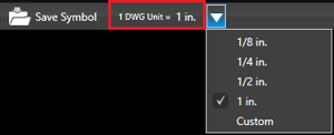 Scale: The AutoCAD scale drop down box is located in the center of the AutoCAD view. From the drop down menu you can set the length of the dwg units. You can choose one of the common lengths or set a custom scale.
Printing Scale: The AutoCAD scale is the drawing scale. The drawing scale and the printing scale are different. In both AutoCAD and Vip3D you choose your printing scale when actually printing your design, not during the design process.
AutoCAD Options
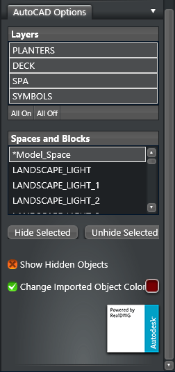 The AutoCAD Options section is located in the Panel. It contains several controls for the AutoCAD view.
Layers: This box lists all the layers in the AutoCAD file. You may hide and unhide the layers in this box.
Spaces and Blocks: This box lists all the Spaces and Blocks in the AutoCAD file. You may select the different spaces and blocks from this list.
Hide Selected: This button will hide the line or shape currently selected in the AutoCAD view.
Unhide Selected: This button will unhide the hidden line or shape currently selected in the AutoCAD view. To use this button you will have to turn on Show hidden objects and Make hidden objects selectable.
Show Hidden Objects: Turning this option on will show lines and shapes which have been hidden in the AutoCAD view. The color of these lines and shapes can be chosen using the color button to the right of the check box.
Change imported object color: With this option turned on, lines and shapes will change color when imported from the AutoCAD view into the Vip3D project. The color of imported objects can be chosen by using the color button to the right of the check box.
Layers:
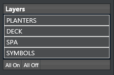 The Layers box lists all of the layers in the AutoCAD file. The number of layers used and the names for each layer are chosen while the file is being created in the AutoCAD program. Vip3D simply imports the information already contained in the AutoCAD file. If you do not create your own AutoCAD files you may find that files you import do not use layers or use confusing layer names.
Layer Names: Layer names are chosen when the file is created in the AutoCAD program. It is not possible to change the layer names in Vip3D. Vip3D simply copies the layers and names saved in the AutoCAD file.
Selecting and Hiding Layers: Layers may be selected by left clicking on their name. Highlighted layers are selected and currently visible in the AutoCAD view. Layers that are not highlighted are not selected and are hidden in the AutoCAD view. You may have all or none of the layers visible when working in the AutoCAD view. NOTE: The controls for hiding layers are different from the controls for hiding objects.
All On: This button will select all of the layers in the list and make all the layers visible in the AutoCAD view.
All Off: This button will unselect all the layers in the list and hide all the layers in the AutoCAD view.
Spaces and Blocks:
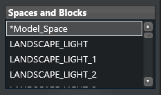 The Spaces and Blocks box lists the spaces and blocks contained in the AutoCAD file. Spaces represent the main design and any construction pages created for printing. The blocks represent templates used in the AutoCAD file and often include landscaping symbols. Vip3D simply imports the information already contained in the AutoCAD file.
Spaces and Blocks Names: The names for the Model Space and Paper Spaces are standard for AutoCAD files. The block names are chosen when the blocks are created. It is not possible to change these names in Vip3D. Vip3D simply copy the names in the AutoCAD file.
Model Space: In AutoCAD files, the Model Space is the main drawing. The Model Space is nearly the same as the 2D view in Vip3D. All AutoCAD files will have a Model Space. Nearly everything you will be importing from the AutoCAD file will be found in the Model Space. The majority of the time you are working in the AutoCAD view you will be working in the Model Space.
Paper Spaces: In AutoCAD files, the Paper Spaces are construction plans prepared for printing. The Paper Spaces are nearly the same as the Construction Stage in Vip3D. Not all AutoCAD files will have Paper Spaces. You will primarily import from Paper Spaces when working in the Construction Stage.
Blocks: In AutoCAD files, Blocks contain templates and symbols especially for plants and trees. Selecting a Block from the list will display just the contents of that one Block in the AutoCAD view. This makes it easy to import templates and symbols from the AutoCAD file into the Vip3D library. Symbols can only be saved into the Vip3D library by pressing the Save Symbol button or in Construction Markup.
 Selecting Symbols and Templates from the Spaces and Blocks Box: When a block is selected, only the contents of that block, the template or symbol, will appear in the AutoCAD view.
Saving Templates from Blocks to the Vip3D Library: Once a symbol or shape from the AutoCAD view is imported it may be selected and saved to the library.
It is important that all templates be imported into the correct stage. For example, house templates need to be imported to the House Stage and saved to the library from that stage.
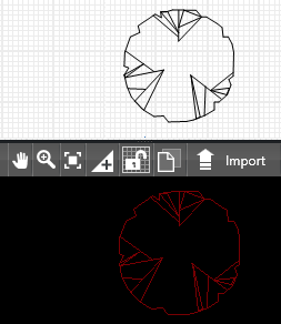
Line Colors in the AutoCAD View
Vip3D does not import line colors from the AutoCAD file. When the file is loaded in the AutoCAD view all the lines will be white. Importing and hiding lines may change the line colors based on the settings you select under AutoCAD Options.
Imported Object Color: When the Change imported object color box is checked under AutoCAD Options, lines and shapes in the AutoCAD view will change color when imported. This makes it easy to see which shapes have already been imported into the project. The imported object color may be changed by using the color button to the right of the check box.
Hidden Object Color: When the Show hidden objects box is checked under AutoCAD Options, lines and shapes that have been hidden in the AutoCAD view will appear. These hidden objects will be revealed and have a different line color, to set them apart from the other objects in the AutoCAD view. If the objects are unhidden, the line color will change back to white. The line color for hidden objects may be changed by using the color button to the right of the check box.
Displaying the AutoCAD View as a Background Image
Some lines and shapes in the AutoCAD file may have been drawn in such a way as to be impractical to import into the Vip3D project. For instance, an arc may have been drawn as several small straight lines. Such an arc would be difficult to weld into a complete shape in Vip3D. Since it is simply easier to redraw the arc, the AutoCAD view can be displayed as background image to use as a guide for tracing.
NOTE: This feature is also available in the Construction Markup Stage.
.png?width=246&name=AutoCAD-Display-View%20(1).png) Display AutoCAD View as Background Image: Pressing this button will collapse the AutoCAD view and display it as a background image.
Display AutoCAD View as Background Image: Pressing this button will collapse the AutoCAD view and display it as a background image.
Position and Scale of the AutoCAD Background Image: The AutoCAD view will be displayed as a background image on the 2D grid. The scale and the position of the background image will be determined by the position of the reference points and the AutoCAD scale. Moving the reference point on the grid or adjusting the AutoCAD scale will change how the background image appears.
![]() Returning to the AutoCAD View: The Display AutoCAD view as Background Image button will appear at the top of your screen on the 2D View tool bar while the AutoCAD view is displayed as a background image.
Returning to the AutoCAD View: The Display AutoCAD view as Background Image button will appear at the top of your screen on the 2D View tool bar while the AutoCAD view is displayed as a background image.
Pressing the button will remove the background image and return to the normal AutoCAD view.
Saving Symbols from AutoCAD to the Library
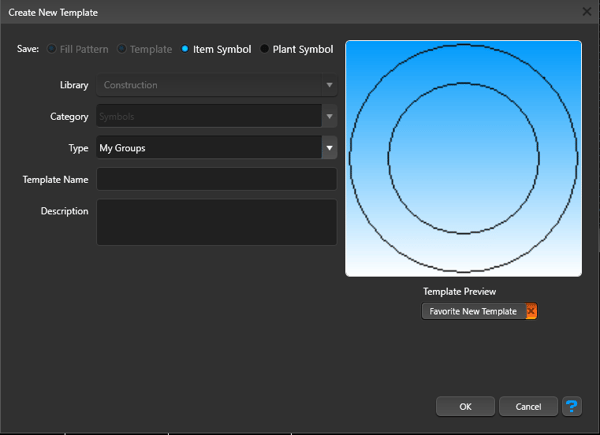
Many blocks in the AutoCAD file are plant and tree symbols. These symbols can be saved to the Vip3D library by pressing the Save Symbol button.
.png?width=250&name=AutoCAD-Save-Symbol%20(1).png) Once saved to the library, these imported symbols may be assigned to plants and trees and other items in the library.
Once saved to the library, these imported symbols may be assigned to plants and trees and other items in the library.
It is very important that you save the symbol as an Item Symbol or Plant Symbol.
Once the symbol has been saved, it may now be assigned to plants and trees and other items in the Library.
In the library, select the item you would like to assign to the new symbol. Press the Edit button to bring up the Edit Object box. The new symbol will now appear under the name you gave it in the symbol list. Select the symbol from the list and assign it to the library item. If you are editing a plant or tree, you may assign the symbol to any of the container classes. Click Ok, and the library will now use the new symbol for that item.
For more information, please see the Plants and Trees and Construction Markup stages.