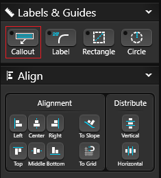
Keep your design organized and presentable with Labels and Guides.
Callout Label
The callout tool gives you the option to automatically add the object name and material name of any drawn shape or library item.
Using Callout: Select a drawn shape or library item and click Callout guide. This will add automatically add a text label and arrow with the object name and material name. With the move tool, the arrow may be adjusted to point to any location in the viewport. The center point of the arrow may also be adjusted to make it bend. The color of the arrow will be the same color as the text.
Callout Information: The object name is pulled from the name field in Object Properties. The material name is the name of the material applied from the library. To hide either the object or material name, uncheck the box on the Text/Font tab.
Renaming Callout: To change the content of the Callout Label, double left click on the text, then type in the field.
A popup box will ask you to verify if you would like to change all labels to match. Click Yes to change all Callout Labels and Legends for the selected object, or click No to only change the selected object.
Please Note: To display custom content make sure to add a checkmark in the panel for Object Name and Material Name.
Image Callout Label
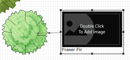
With the Callout Tool, you can also add photos to plants and site objects. This is a great way to share your plant palette and project details with your clients.
Add the Callout:
1. Select the Plant, Tree or Library object, then Callout under Guides.
2. Next under Object Settings, check the box for Image.
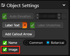
3. Double click on the image to access the menu, or click Edit in the Library.
Assign the Image:
You can select images saved on your PC, click Online Search to look for new images, or drag and drop images from your browser.
- Browse PC: Clicking on Browse PC will bring up a file selection box. Graphic files in the .BMP, .PNG, .JPG, or .TGA formats may be used.
- Online Search: Clicking on Online Search will open your default browser, and search for the Botanical name or Template Name of the object. The image can be saved to the PC, or dragged into the “Drag image here” area in the object menu.
NOTE: You may need to view the original image before dragging. Click to view the larger preview of the image in your browser, then View Image. Some images cannot be dragged or saved, depending on the website’s security settings.
Change Label
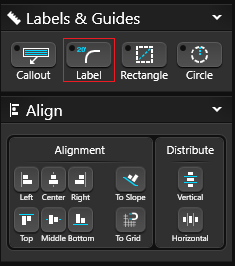 The change label tool allows you to move your measurements to any location on the shape or even away from the shape.
Using Change Label: Click on the measurement with Change Label selected to change the location. A dotted line will appear linking it to the shape or segment.
Showing Measurements: To hide the measurements in Construction Markup, select the label and press the Hide Selected Button or CTRL + H.
Rectangle Guide
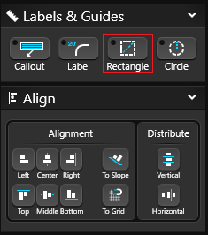 The rectangular guides are for creating sketch lines and are seen only in the 2D viewport. They will appear when the 2D view is printed, but they are not represented in 3D or Presentation mode.
Drawing Rectangular Guides: Position the cursor in the viewport, single-click the left mouse button to set one corner of the rectangle. The cursor then represents the opposite corner of the rectangle. Move the mouse to adjust size and shape of the rectangle. Single-click the left mouse button to set the rectangle guide.
Showing Measurements: To show measurements, check the Display Measurements box located under the Object Tab. To hide the measurements, uncheck the box and a red X will appear.
Circle Guide
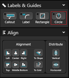 The circular guides are for creating sketch lines and are seen only in the 2D viewport. They will appear when the 2D view is printed, but they are not represented in 3D or Presentation mode.
Drawing Circular Guides: Position the cursor in the viewport and single-click the left mouse button to set one point of the circular guide. Move the cursor away from the point to create a circle. Single-click the left mouse button to set the circular guide.
Showing Measurements: To show measurements, check the Display Measurements box located under the Object Tab. To hide the measurements, uncheck the box and a red X will appear.
Align Tools
Alignment Options
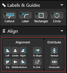
Left: Selected objects will align to the left most object.
Center: Selected objects will be centered vertically.
Right: Selected objects will align to the right most object.
Top: Selected objects will align to the top most object.
Middle: Selected objects will be centered horizontally.
Bottom: Selected objects will align to the bottom most object.
To Slope: Selected objects will align to the slope of the terrain.
To Grid: Selected line or shape will align to the closest grid line.
Distribute Options
Distribute Vertical: Selected objects will be evenly spaced vertically.
Distribute Horizontal: Selected objects will be evenly spaced horizontally.
Align to Grid
With just a click of the Align to Grid button, you can adjust the position of your line or shape to align automatically with the grid lines. This handy tool saves you time and ensures precision in your drawings, helping you make sure all elements are evenly spaced and aligned.